Choosing Carbon Steel Welding Electrodes requires more than matching a number to a steel grade. The joint position, material thickness, welding current, and service conditions all influence the result. A suitable electrode should create a stable arc, dependable fusion, and a weld profile that inspectors can evaluate clearly. In practical workshop work, an electrode that performs well on a flat plate may behave poorly overhead. Small differences matter.
Common options include E6010, E6011, E6013, and E7018. E6010 offers deep penetration and is often used with direct current on prepared joints. E6011 can be useful where alternating current is available. E6013 usually provides a smoother arc for general fabrication and lighter work. E7018 supports stronger, low-hydrogen welds when storage and handling are properly controlled. However, these descriptions are not enough. Always check the electrode classification, manufacturer instructions, welding procedure, and applicable standards, such as AWS requirements.
The best choice also depends on the welder’s technique. That is easy to overlook. An electrode may be technically suitable but difficult to control in an awkward position. Moisture, poor cleaning, excessive travel speed, and incorrect amperage can cause porosity, undercut, or incomplete fusion. Before production welding, test the electrode on comparable steel and inspect the bead’s shape, penetration, and slag removal. No selection guide replaces qualified judgment. Even experienced welders sometimes choose too quickly, then discover that the joint design—not the electrode—was the real problem.
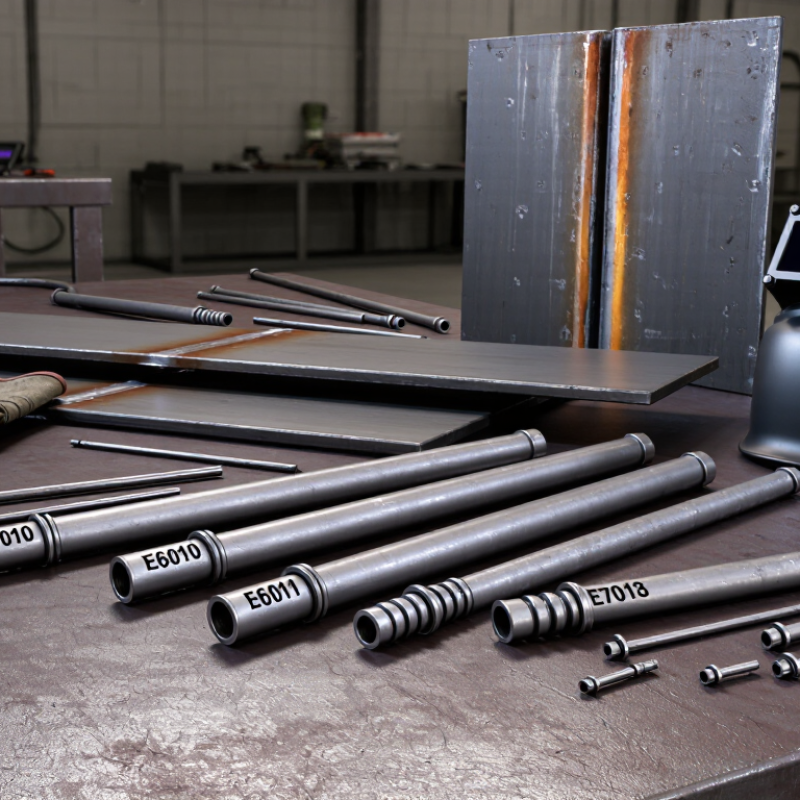
Carbon steel electrodes are identified by classification codes, not by appearance alone. In AWS designations, “E” means electrode, while the following numbers show strength and welding position. For example, E6013 offers 60 ksi minimum tensile strength and supports common positions. The final digit indicates coating type and suitable current. E7018 provides higher strength and a low-hydrogen coating, making it useful for restrained joints and demanding structures. However, code interpretation can vary by specification, so always verify the applicable welding standard.
Check the base metal, joint design, thickness, position, and power source before choosing an electrode. E6010 can create a forceful arc and deep penetration, which suits root passes on suitable steel. E6013 usually gives a smoother arc and easier slag removal for general fabrication. E7018 needs careful storage because moisture can increase hydrogen-related cracking risk. A dry electrode is not automatically the right electrode. I have seen good welders select by habit, then struggle with vertical beads or excessive spatter.
Tips: Read the electrode package and welding procedure together. Match the electrode diameter to material thickness and heat control. Confirm polarity before striking the arc. Keep a small test plate nearby, and inspect the bead profile, slag release, and fusion. If the result looks acceptable, check again; appearance alone can hide incomplete penetration or undercut. Some decisions remain uncertain until the joint design and service conditions are fully understood.
“E” means electrode. The numbers indicate tensile strength and suitable welding positions. The final digit identifies coating and current compatibility. For example, E6013 offers 60 ksi minimum tensile strength. Always check the applicable specification.
E6010 produces a forceful arc and deep penetration. It can suit root passes on compatible steel. E6013 provides smoother handling and easier slag removal. E7018 offers higher strength and low-hydrogen performance. Selection depends on the joint, position, and procedure.
No. Moisture control matters, especially with low-hydrogen electrodes. Damp storage may increase hydrogen-related cracking risk. However, a dry electrode can still be unsuitable. Match it to the steel and joint.
A 2.5 mm electrode commonly suits 3–5 mm plate. A 3.2 mm electrode often suits 6–10 mm joints. A 4.0 mm electrode may support thicker, multi-pass sections. These are starting points, not fixed rules.
Typical direct-current ranges are 60–90 A for 2.5 mm electrodes. Use 90–130 A for 3.2 mm electrodes. Use 130–180 A for 4.0 mm electrodes. Verify the electrode data sheet and approved procedure.
Low current may cause poor fusion and a tall bead. High current can enlarge the weld pool. It may create undercut or burn through thin steel. Watch the puddle. The arc should sound steady.
A narrow gap or difficult position may require a smaller electrode. Root face, joint gap, and thickness also influence heat control. A larger electrode may weld faster. I have chosen one for speed, then repaired distortion later.
Make a short test weld on matching scrap. Inspect bead profile, slag removal, fusion, and edge condition. A clean surface can still hide incomplete penetration. Look again. Visual appearance alone is not enough.
Choosing the right Carbon Steel Welding Electrodes requires more than selecting a common electrode type. Start by understanding electrode classifications and designations, which indicate tensile strength, welding position, coating characteristics, and operating requirements. The electrode’s strength and chemical composition should be compatible with the base metal to reduce the risk of cracking, weak joints, or excessive distortion. Coating type is also important because it affects arc stability, slag removal, moisture resistance, and performance under different welding conditions.
Next, match the electrode diameter and current settings to the joint thickness, groove design, and desired deposition rate. Consider whether the work will be performed in flat, horizontal, vertical, or overhead positions, since some electrodes provide better control in specific orientations. Proper storage is essential, especially for moisture-sensitive coatings, so electrodes should be kept in suitable, dry conditions. Finally, verify that the selected electrodes and welding procedures comply with applicable industry standards and project specifications for safe, consistent, and reliable results.

 Tianqiao Welding